RL circuit
An RL circuit is a basic electrical circuit made by connecting a resistor (R) and an inductor (L) in series with a power supply. This setup is known as an RL Series circuit and is commonly used to study how current and voltage behave when inductance is involved. In an RL circuit, the inductor resists sudden changes in current, creating a time delay as the current gradually increases or decreases. This property makes RL circuits useful in filters, signal processing, and timing applications.
RL series circuit diagram
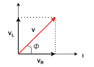
To construct the phasor diagram, the rms current I (rms value) is taken as the reference vector. The voltage drop across the resistor $V_{R}=I_{R}$ is in phase with the current, while the voltage drop across the inductor $V_{L}=I_{L}$ leads the current by $90^\circ$, as the current lags behind voltage in a purely inductive circuit. The vector sum of these two voltages represents the total applied voltage V (rms value) in the circuit.
Phasor Diagram
Derivation of Impedance in RL Series Circuit
The voltage across the resistor is in phase with the current:
$\displaystyle V_R=IR$
The voltage across the inductor leads the current by $90^\circ$:
$\displaystyle V_L = I X_L = I \omega L$
Total Voltage (Phasor Sum)
Since $V_R$ and $V_L$ are perpendicular to each other in the phasor diagram (i.e., $V_L$ leads $V_R$ by $90^\circ$), the total voltage $V$ is given by the Pythagorean sum:
$V = \sqrt{V_R^2 + V_L^2}$
Substituting $V_R = IR$ and $V_L = I \omega L$:
$V = \sqrt{(IR)^2 + (I \omega L)^2}$
Factoring $I$:
$V = I \sqrt{R^2 + (\omega L)^2}$
Then the voltage can be written as:
$V = I Z$
Impedance
$\boxed{Z = \sqrt{R^2 + (\omega L)^2}}$
Derive the formula of Power in RL Circuit
\( v(t) = V_m \sin(\omega t) \)
\( i(t) = I_m \sin(\omega t - \phi) \)
$p(t) = v(t) \cdot i(t) = V_m \sin(\omega t) \cdot I_m \sin(\omega t - \phi)$
Using the trigonometric identity:
$\displaystyle \sin A \cdot \sin B = \frac{1}{2} \left[ \cos(A - B) - \cos(A + B) \right]$
Apply it:
$\displaystyle p(t) = \frac{V_m I_m}{2} \left[ \cos(\phi) - \cos(2\omega t - \phi) \right]$
Average Power Over a Cycle
The average power over a full cycle is the mean of \( p(t) \). Since the average of the cosine term \( \cos(2\omega t - \phi) \) over one full cycle is zero:
$\displaystyle P_{\text{avg}} = \frac{V_m I_m}{2} \cos\phi$
Now convert peak values to RMS values:
$\displaystyle V_{\text{rms}} = \frac{V_m}{\sqrt{2}}, \quad I_{\text{rms}} = \frac{I_m}{\sqrt{2}}$
Then:
$P_{\text{avg}} = V_{\text{rms}} I_{\text{rms}} \cos\phi$
$\boxed{P_{\text{avg}} = V I \cos\phi}$
Power Factor
The power factor (PF) is defined as the cosine of the phase angle between the voltage and current:$\text{Power Factor} = \cos\phi$
Phase Angle$(\phi):$
From the phasor diagram, the phase angle $\phi$ is given by:
$\displaystyle \phi = \tan^{-1} \left( \frac{X_L}{R} \right)$
Interpretation
- $X_L = 0$, then $\cos\phi = 1$ (unity power factor).
- $X_L$ increases, $\cos\phi$ decreases (lagging power factor).
- The power factor indicates the efficiency of power usage in the circuit.

